


Rapid, cost-effective prototyping and production parts is often a balance between a quick shift to CNC machining capabilities and optimized parts designed for those capabilities. As a result, here are 6 important considerations when designing parts for milling and turning processes that can speed up production time while reducing costs.
1. Hole Depth and Diameter
Holes in most cases are interpolated with end mills rather than drilled. This method of machining offers great flexibility in terms of hole size for a given tool and provides a better surface finish than drilling. It also allows us to machine slots and cavities with the same tool, reducing cycle time and part cost. The only drawback is that due to the limited length of the end mill, holes deeper than six diameters become a challenge and may need to be machined from both sides of the part.
2. Thread Size and Type
Drilling and thread making go hand in hand. Many manufacturers use a "tap" to cut internal threads. The tap looks like a screw with teeth and "screws" into the previously drilled hole. We use a more modern method of making threads, a tool called a thread milling cutter to insert the thread profile. This creates accurate threads and saves production and installation time by allowing a single milling tool to cut any thread size (threads per inch) that shares that pitch. As a result, UNC and UNF threads from #2 to 1/2 inch and metric threads from M2 to M12 are available in a single toolset.
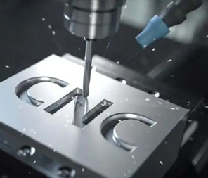
3. Engraving on parts
Want to engrave part numbers, descriptions or logos on your parts? Sega supports most of the text needed for machining, provided that the spacing between individual characters and the stroke used to "write" them is at least 0.020 inches (0.5 mm). In addition, text should be concave rather than raised, and a font of 20 points or larger, such as Microsoft Black, Microsoft YaHei, Verdana, or a similar sans-serif font, is recommended.
4. Wall height and feature width
All of our tools consist of carbide cutters. This ultra-rigid material provides maximum tool life and productivity with minimal deflection. However, even the strongest tools can deform, as can metals and especially the plastics being machined. As a result, wall heights and feature sizes are very dependent on the geometry of the individual part as well as the tool set used. For example, support for machining a minimum feature thickness of 0.020 inches (0.5 mm) and a maximum feature depth of 2 inches (51 mm) does not mean that you can design a ribbed radiator using these dimensions.
5. Power Tool Lathe
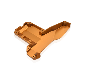
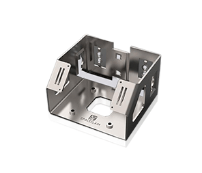
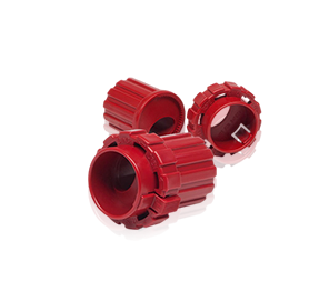
In addition to our extensive milling capabilities, we also offer live tool CNC turning. The tool sets used on these machines are similar to those used on our machining centers, except that we do not turn plastic parts at this time. This means that eccentric holes, slots, planes and other features can be machined parallel or perpendicular (axial or radial) to the "long axis" of the turned part (its Z axis) and generally follow the same design rules as orthogonal parts made on machining centers. The difference here is the shape of the raw material, not the tool set itself. Turned parts such as shafts and pistons start out round, whereas milled parts such as manifolds, instrument cases, and valve covers usually do not, and instead use square or rectangular blocks.
(Parts shown here are made on a CNC lathe with power tools)
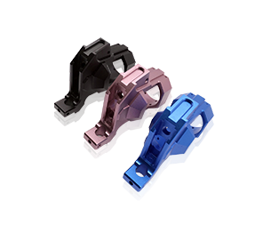
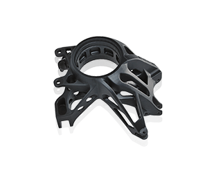
6. Multi-Axis Milling
Using 3-axis machining, the part is clamped from the bottom of the raw stock blank while all part features are cut from up to 6 orthogonal sides. Part sizes larger than 10 inches * 7 inches (254 mm * 178 mm) can be machined top and bottom only, with no side setups! However, with 5-axis indexed milling, it is possible to machine from any number of non-orthogonal sides.
(For parts using 5-axis machining, this illustrates how the part fits into the material block using the maximum part extent of 2 inches wide and 2 inches high)
The tool set used is the same in both cases. The difference is the raw material. As with our lathe, round blanks are used for 5-axis milling of the part, which makes for some interesting mathematical discussion of the size, geometry, and location of the part within the raw material volume (this is the whole Hook Theorem you learned in high school). For some examples of this, you can stare at the accompanying diagrams for a while, or just upload your part model online at protolabs.com.