


The concepts of part interchangeability and dimensional tolerances have become an accepted part of manufacturing. Unfortunately, misuse of the latter can lead to a host of problems. For example, tolerances that are too tight may require the part to undergo a secondary grinding or EDM operation in order to be completed, unnecessarily increasing costs and lead times. Tolerances that are "too loose" or inconsistent with those of mating parts can prevent assembly, resulting in the need for rework or, at worst, rendering the finished product unusable.
To avoid these unpleasant situations, this Design Tip includes some guidelines on how to properly apply part tolerances, as well as definitions of some of the more commonly used markings. We will also look at the industry standard for part tolerances, called Geometric Dimensioning and Tolerancing (GD&T).
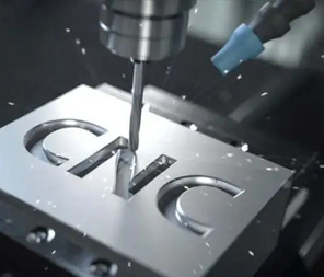
1. Standardized tolerances for CNC machining
Assume standard prototype and production machining tolerances of +/-0.005 inches (0.13 mm). This means that the position, width, length, thickness, or diameter of any part feature will not deviate from the nominal value by more than that. If the plan is to machine a 1-inch (25.4 mm) wide bracket that will measure between 0.995 and 1.005 inches (25.273 and 25.527 mm) and the bracket has a 0.25-inch (6.35 mm) hole in one of the legs, the bracket will have a diameter of 0.245 to 0.255 inches (6.223 to 6.477 mm), as shown below.
This is very close, but if you need higher accuracy, which needs to be judged based on the geometry and material of the part, be sure to indicate this in the part design when uploading the file for a quote.
2. CNC Machining Tolerance Guide
Also, please note that these are bilateral tolerances. If expressed in one-sided terms, the standard tolerance should be +0.000/-0.010 in. (or +0.010/-0.000 in.). All of these are acceptable, as are metric values, as long as you detail them in your design. To avoid confusion, follow the "three-bit" dimensions and tolerances shown, and avoid the extra 1.0000 or 0.2500 in. zeros. Avoid extra zeros of 1.0000 or 0.2500 inches unless there is an absolute reason to do so.
3. Surface Roughness Considerations for Machining Tolerances
In addition to length, width, and hole dimensions, there are also part tolerances such as surface roughness. For standard products, surface roughness for flat and vertical surfaces is equal to 63 µin. and curved surfaces are better equal to 125 µin.
This is a sufficient finish for most uses, but for decorative surfaces on metal parts, we can usually improve the appearance with light sandblasting. If you require a smoother surface, please indicate this in your design and we will do our best to meet your requirements.
4. Geometric dimensions and tolerances
There is one more consideration. As mentioned earlier, we can accept GD&T tolerances. This provides a deeper level of quality control, including the relationship between various part features and shape and fit qualifiers. Here are some of the more common methods:
TRUE POSITION: In the bracketed example quoted earlier, we labeled the hole position by specifying the X and Y distances and their allowable deviations from a pair of perpendicular part edges. In GD&T, the hole location will be represented by the true position of a set of reference datums with qualifiers MMC (Maximum Material Condition) or LMC (Minimum Material Condition).
Flatness: milled surfaces are usually very flat, but due to internal material stresses or clamping forces during machining, some warpage may occur after the part is removed from the machine, especially on thin-walled and plastic parts. gd&t flatness tolerance controls this by defining the two parallel planes in which the milled surface must be located.
Cylindricity: For the same reason that most milled surfaces are very flat and most holes are very round, the same is true of turned surfaces. However, using a +/-0.005-inch (0.127-mm) tolerance, the 0.25-inch (6.35-mm) hole in the bracket example may be rectangular, with the other unidirectional dimensions of 0.245-inch (6.223-mm) and 0.255-inch (6.477-mm). Using cylindricity defined as two concentric cylinders in which the machined hole must be located eliminates this unlikely scenario for the manufacturer.
Concentricity: The rings on the bullseye are concentric, just as the wheels on an automobile are concentric with the axle. If a drilled or reamed hole must be perfectly aligned with a coaxial countersunk hole or round boss, a concentricity marking is the best way to ensure this.
Perpendicularity: As the name implies, perpendicularity determines the maximum deviation of a horizontally machined surface from a nearby vertical surface. It can also be used to control the perpendicularity of a turned shoulder to an adjacent diameter or the center axis of the part.
So what are the differences between our machining options? First of all, quotes for high precision/high volume machining are not as automated as our automated machining options, so quotes may need to be reviewed manually. With high precision machining, there is also a slightly longer lead time for finished product delivery. We require 3D CAD models, as well as 2D drawings with GD&T tolerances. This may also mean that we go beyond our standard set of cutting tools and use machining processes such as wire EDM, EDM opening, grinding and boring to meet your part quality requirements.
Additionally, SHOWY is ISO 9001 certified, and upon request, we will perform a 100% full inspection of your parts, as well as provide quality inspection reports, First Article Inspection (FAI), material certifications, and more. If you have parts to be machined, you can upload drawing files through the intelligent quotation system on SHOWY's official website, and we will provide you with automatic quotations, as well as arranging professional pre-sales engineers to serve you.