


In today's world, products are becoming more complex and overall pricing is under downward pressure. This has led to an inevitable increase in the geometric complexity of mechanical components. While this allows components to perform multiple functions, it also leads to complex load transfer and possible stress concentrations.
Stress concentrations are defined as high localized stresses compared to the average stresses in the body and are usually found in regions with abrupt geometric changes. This paper will introduce the basics of stress concentrations, provide practical examples to illustrate the concept, and outline ways to reduce stress concentrations in design.
Overview of Stress Concentration
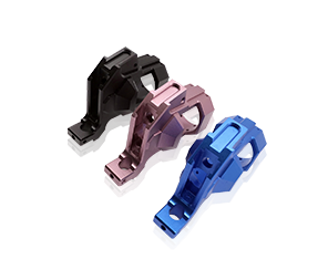
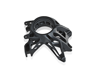
Stress concentrations are relatively simple when it comes to determining where they are located and whether they are causing a failure. They will be located at small radii and sharp corners in the tension path. The figure below shows an assembly that has rollers on smaller diameter shafts at each end of the assembly and applies tension to the top plane.
This setting will be almost like a skateboard truck, but we will be subjected to higher cyclic forces. Below is a rendering of the component (including the rollers with bearings) where the part is located.
The smaller diameter shaft intersects the center portion of the roller support with a relatively steep radius. If we zoom in on this radius, we can see that it is only 0.010 inches as follows
As mentioned above, the acute angle or radius will be the location of the stress concentration. To visualize this stress concentration, I will run an FEA study which will map out these stresses nicely.
We have a 500 pound downward force and have secured the surface of the shaft where the roller is. The only step left is to run the simulation and process our beautiful images! In the image below we can see beautiful red spots, representing stress concentrations.
We can see that this is the highest stress feature and this will be the first failure location under cyclic tension (although it is most likely to occur on the bottom side which is in tension, rather than the top compression side). It will start as a small surface crack and eventually propagate through the component to complete failure.
There are some basic formulas to define the maximum stress in such geometry when we apply a bending moment. The formula in this example is as follows:
σmax=kt*σave
Among them: K, t = stress concentration coefficient; σ,ave = average stress in the component
In many simple geometries, the stress concentration factor is defined for a range of geometries. The graph below shows the curves of these factors and the dependence on the critical dimension ratio.
When using this chart, first divide the major diameter by the minor diameter. Let's say we have a 2-inch diameter rod that's dropped to 1 inch; this gives us a D/d of 2. Next, we look at the ratio of radius to smaller diameter.
As another example, assuming a radius of 0.1 inches, the r/d ratio is 0.1. If we look at the graph above, we need to find the curve that represents D/d as 2. Then we look at the x-axis and determine r/d is 0.1, and look at the y-axis and get a stress concentration factor of about 1.8.
The image shows all of this as follows:
It is important to note that this formula changes depending on the tension situation and geometry, so I encourage you to further explore graphs for other geometries. Now that we understand the basics, we can get into some examples of correcting stress concentrations.
real example
In this section we will look at some practical examples and how to reduce peak stresses at locations of stress concentration. The first example we're going to look at is the original assembly with rollers. If you remember, we had a very small 0.01 inch radius as the diameter increased. Now we will increase the diameter to 0.08 inches and see how much we can reduce the stress.
The first picture is the original stress and the second picture is the stress reduced at a larger radius.
We can see that the stress decreases from 14,419 psi to 3,873 psi. Although this difference is extremely extreme due to the very small initial radius, it informs us about the extent of stress concentration on the component.
Some general guidelines and issues to avoid are as follows:
When it comes to common methods for stress relief, the following list includes some simple items to get you started quickly:
1,Maximize the radius in the tension path.
2,Restrict the ratio between large and small features whenever possible.
3,Add relief holes at the ends of narrow slots, sharp corners, or cracks to alleviate high stress concentrations.
Some common issues to avoid include:
1,Avoid sharp corners in the tension path.
2,Avoid large size transitions between features in the tension path. Stiffness mismatch will lead to higher stress concentration.
3,Do not assume the same size radius applies to all features. Remember that stress concentration is based on a ratio, not a size.
4,If you absolutely must use sharp corners, do not place stress concentration in high cyclic tension.
As you may have already guessed, most don'ts are the opposite of dos. This list is not comprehensive, but it should cover the basic concepts that every designer should know to enhance their design skills.
Through the examples and analysis above, we should clearly understand why we need to pay attention to stress concentration. By incorporating these concepts into the design, you should be able to achieve higher rated tension, reliability, and fatigue life.